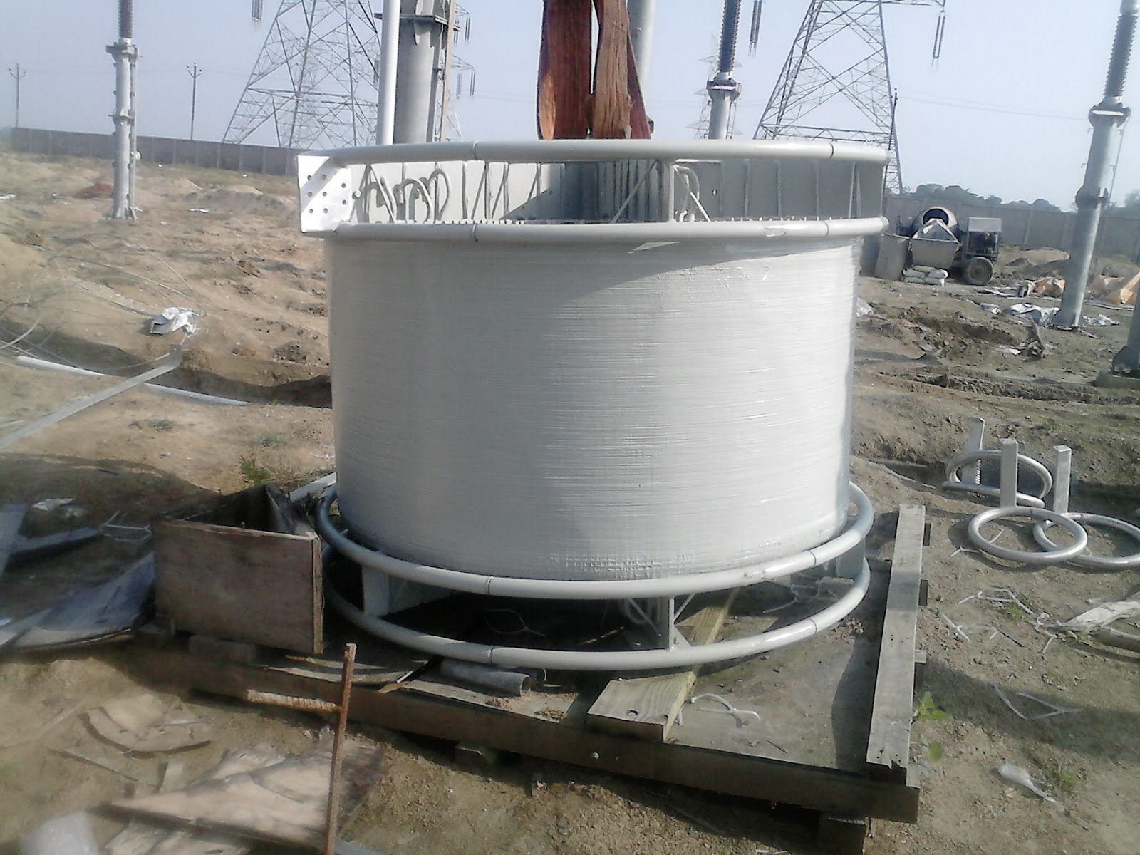
Wave Trap Magic: Taming Unwanted Frequencies
Ever wonder how radios manage to pick out your favorite station amidst a sea of electromagnetic waves? Or how power lines prevent unwanted frequencies from disrupting the grid? The answer often lies in a clever bit of circuitry called a wave trap. These nifty devices, also known as frequency traps or band-stop filters, are designed to selectively block specific frequencies while allowing others to pass through unimpeded. This article will delve into the fascinating world of wave trap circuits, exploring their design, applications, and importance in various fields.
Wave trap circuits act like gatekeepers for electromagnetic signals. Imagine a bouncer at a club, only allowing people with specific wristbands to enter. The wave trap is the bouncer, and the unwanted frequency is the person without the right wristband. They are crucial in various applications, from radio communications to power distribution, ensuring clean and efficient signal transmission.
The history of wave trap circuits is intertwined with the development of radio technology. As the airwaves became increasingly crowded, the need to isolate desired signals from interfering frequencies became paramount. Early wave traps were often simple LC circuits, consisting of an inductor and a capacitor, designed to resonate and block a specific frequency. Over time, more sophisticated designs emerged, incorporating active components and digital signal processing techniques to achieve even greater precision and control.
A wave trap’s primary function is to eliminate unwanted frequencies, thus improving signal quality and preventing interference. In radio communication, a wave trap might be used to block a strong local station that interferes with a weaker, more distant station. In power systems, they can suppress harmonic frequencies generated by non-linear loads, preventing damage to equipment and improving power quality. Understanding the function and application of a wave trap circuit design is essential for anyone working with electronic systems.
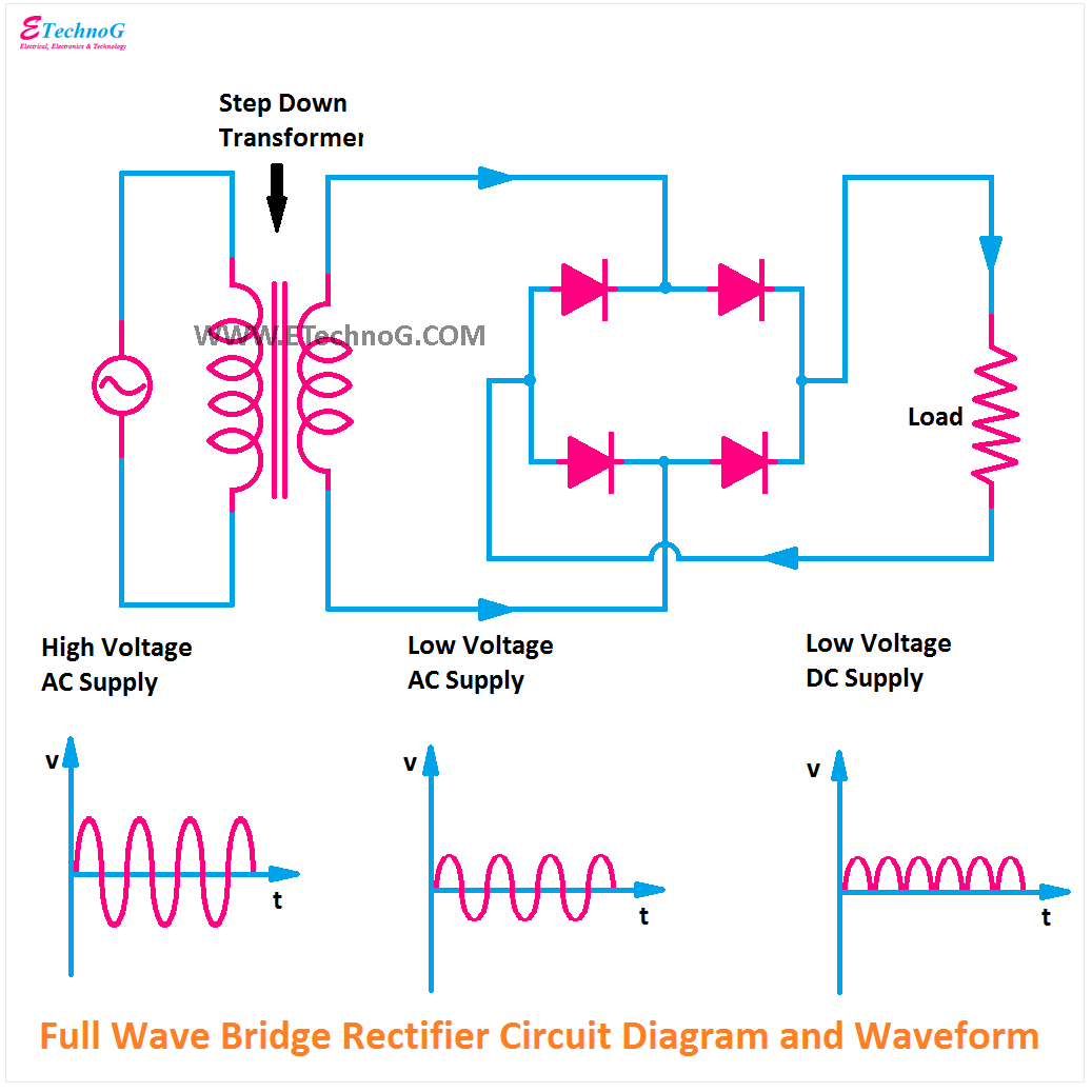
The design of a basic wave trap circuit often centers around a parallel LC resonant circuit. The inductor (L) and capacitor (C) are chosen such that their resonant frequency matches the frequency to be blocked. At the resonant frequency, the impedance of the LC circuit becomes very high, effectively blocking the passage of that specific frequency. Other frequencies, however, encounter a much lower impedance and pass through the circuit relatively unaffected. Analyzing a wave trap circuit diagram reveals the interplay of these components and provides insights into how the circuit achieves its frequency-selective behavior.
One simple example is a wave trap used in a radio receiver to block a strong local AM station. The LC circuit is tuned to the frequency of the interfering station. When the receiver encounters signals from both the desired station and the interfering station, the wave trap effectively attenuates the signal from the interfering station, allowing the desired signal to be heard clearly.
Benefits of using wave traps include improved signal quality, reduced interference, and protection of sensitive equipment. For instance, in power systems, wave traps help maintain the stability and efficiency of the grid by suppressing harmonic frequencies that can damage transformers and other components. In radio receivers, they enhance selectivity and sensitivity, enabling clear reception of weak signals. Finally, in antenna systems, wave traps can optimize performance by suppressing unwanted radiation at specific frequencies.
Advantages and Disadvantages of Wave Trap Circuits
| Advantages | Disadvantages |
|---|---|
| Improved signal quality | Can be sensitive to component tolerances |
| Reduced interference | May introduce slight attenuation at nearby frequencies |
| Protection of equipment | Requires careful design and tuning for optimal performance |
Best Practices for Implementing Wave Trap Circuits:
1. Accurate Component Selection: Choose high-quality components with tight tolerances to ensure accurate tuning.
2. Proper Impedance Matching: Match the impedance of the wave trap to the system impedance for optimal performance.
3. Careful Placement: Place the wave trap as close as possible to the source of the unwanted frequency.
4. Thorough Testing: Test the wave trap circuit under realistic operating conditions to verify its effectiveness.
5. Shielding: Employ proper shielding techniques to minimize the impact of external interference.
Challenges and Solutions:
1. Temperature Sensitivity: Changes in temperature can affect component values and shift the resonant frequency. Solution: Use temperature-compensated components.
Frequently Asked Questions:
1. What is a wave trap? Answer: A circuit designed to block specific frequencies.
2. How does a wave trap work? Answer: It uses a resonant LC circuit to create a high impedance at the target frequency.
3. Where are wave traps used? Answer: In radios, power systems, and antenna systems.
4. What are the benefits of using wave traps? Answer: Improved signal quality, reduced interference, and equipment protection.
5. How do I design a wave trap? Answer: Use appropriate formulas and software tools to calculate component values.
6. What are the challenges of implementing wave traps? Answer: Temperature sensitivity and component tolerances.
7. How do I test a wave trap? Answer: Use a signal generator and spectrum analyzer.
8. Where can I learn more about wave traps? Answer: Textbooks on RF circuit design.
Tips and Tricks: Use online calculators and simulation software to aid in the design and analysis of wave trap circuits. Experiment with different component values to fine-tune the performance of your wave trap.
In conclusion, wave trap circuits are essential components in various electronic systems, playing a crucial role in ensuring clear and efficient signal transmission. From radios to power grids, these ingenious devices selectively eliminate unwanted frequencies, enhancing signal quality, preventing interference, and protecting sensitive equipment. By understanding the principles behind wave trap circuit diagrams and implementing best practices, engineers can harness the power of these circuits to optimize the performance of a wide range of electronic applications. Whether you're a hobbyist building a radio receiver or a professional designing a power system, a thorough understanding of wave trap technology is a valuable asset. Continue to explore this fascinating field, and discover the many ways wave traps can enhance the performance and reliability of your electronic designs. Exploring resources like textbooks and online forums can greatly enhance your understanding and expertise in working with wave trap circuits, enabling you to tackle complex design challenges and optimize your electronic projects. Dive deeper into the world of frequency filtering and unlock the potential of these powerful circuits.
Diving deep into the light novel world
The allure of sw 6990 caviar a deep dive into sherwin williams timeless hue
Conquering the road mastering dodge 3500 lug nut torque specs


