Unlocking the Secrets of Half Wave Rectifier Circuits in Tinkercad
Have you ever wondered how your phone charger transforms AC power from the wall into the DC power your device needs? The answer lies, in part, with a clever little circuit called a half wave rectifier. And thanks to tools like Tinkercad, exploring this fundamental building block of electronics has never been easier. Imagine being able to build and test circuits virtually, without needing a physical breadboard or components. That’s the power of Tinkercad, and it’s the perfect platform for diving into the world of half wave rectification.
A half wave rectifier circuit, at its core, is a gatekeeper. It allows only one half of an alternating current (AC) waveform to pass through, effectively "clipping" the negative portion. This results in a pulsating direct current (DC) output. While seemingly simple, this process is essential in numerous electronic devices. Tinkercad provides a virtual environment where you can construct a half wave rectifier circuit diagram using simulated components like diodes, resistors, and AC power sources. This lets you visualize and experiment with the circuit's behavior without any risk of damaging real components.
The history of rectification goes back to the early days of radio technology. The development of the vacuum tube diode paved the way for practical rectification circuits, which were essential for converting AC signals to DC for use in early radios and other electronic devices. The half wave rectifier, using either a vacuum tube or later a semiconductor diode, became a key component in these systems. Today, while more complex rectifier circuits are often employed, understanding the half wave rectifier remains crucial for grasping the fundamental principles of AC-to-DC conversion.
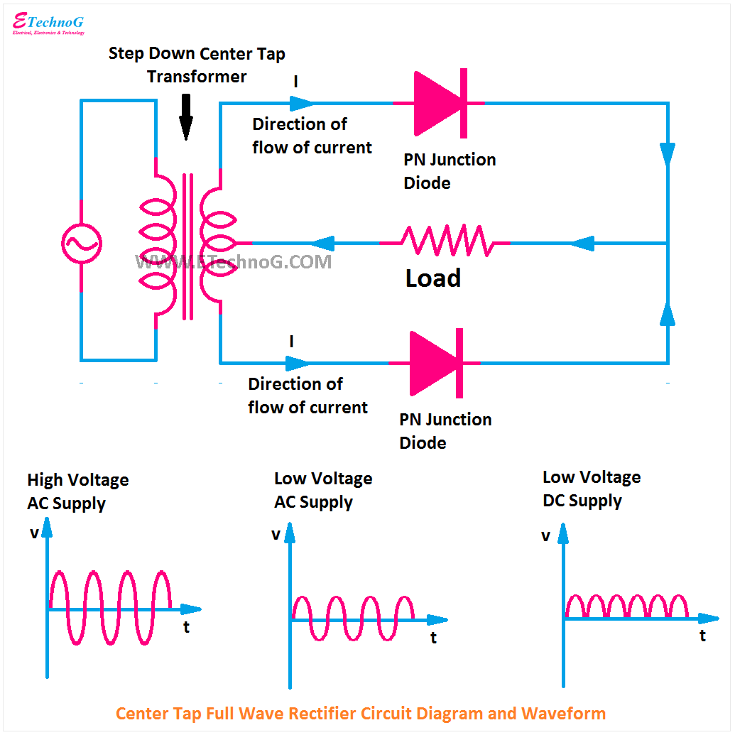
Why is understanding a half wave rectifier circuit important in today's world? While full-wave rectification and more advanced power supply designs are prevalent in modern electronics, the simplicity of the half wave rectifier makes it an ideal starting point for learning about AC-to-DC conversion. It's a gateway to understanding more complex rectifier topologies and power supply designs. By mastering the basics of the half wave rectifier in a simulated environment like Tinkercad, you build a strong foundation for exploring more advanced concepts in electronics.
Simulating a half wave rectifier circuit diagram in Tinkercad offers several advantages. First, it’s risk-free. You can experiment with different component values and configurations without worrying about burning out real components. Second, it’s incredibly visual. Tinkercad’s interface allows you to see the current flowing through the circuit and observe the waveform changes in real-time. Third, it’s accessible. Tinkercad is a free, web-based platform, making it easy for anyone to get started with circuit simulation.
A simple half-wave rectifier circuit comprises an AC source, a diode, and a resistor (representing the load). The diode acts as the gatekeeper, allowing current to flow only when the AC waveform's positive half-cycle is applied. During the negative half-cycle, the diode blocks the current, resulting in zero output. This pulsating DC output across the load resistor can then be visualized using an oscilloscope in Tinkercad.
Benefits of using Tinkercad for half-wave rectifier simulation: 1) Easy visualization of waveforms. 2) Safe experimentation with component values. 3) Accessibility and free usage.
Advantages and Disadvantages of Half Wave Rectifiers
| Advantages | Disadvantages |
|---|---|
| Simple Circuit Design | Low Efficiency (Only utilizes half of the AC wave) |
| Low Cost | High Ripple Content (Output DC is not smooth) |
| Fewer Components | Not suitable for high-power applications |
Best Practices: 1) Use appropriate diode ratings. 2) Choose the right resistor value for your load. 3) Carefully connect components in Tinkercad.
Real-World Examples: 1) Simple battery chargers. 2) AM radio demodulation.
Challenges and Solutions: 1) Ripple in the output can be reduced by adding a capacitor.
FAQs: 1) What is a half wave rectifier? A circuit that converts AC to pulsating DC. 2) What is Tinkercad? A free online platform for circuit simulation.
Tips and Tricks: Use the oscilloscope in Tinkercad to visualize the waveforms.
In conclusion, the half wave rectifier, while a relatively simple circuit, plays a significant role in the world of electronics. Understanding its operation is fundamental to grasping the principles of AC-to-DC conversion. Tinkercad provides a powerful and accessible platform for exploring this essential circuit. Through its virtual environment, you can build, test, and analyze half wave rectifier circuits without the need for physical components. By simulating different scenarios and experimenting with component values, you can deepen your understanding of rectification and its applications. As you progress in your electronics journey, the foundational knowledge gained from exploring half wave rectifiers in Tinkercad will serve as a valuable asset in tackling more complex circuits and systems. So dive in, explore, and unlock the secrets of this fascinating electronic building block. Take advantage of the free resources available online and continue your learning journey in the exciting world of electronics.
Unlocking the truth your guide to toyota rav4 reviews
Unlocking the subtle elegance of gray mist your guide to benjamin moores versatile neutral
Stress free roadside assistance down and out towing and recovery llc

