Unlocking the Power of DPDT Switches: Your Guide to Wiring Diagrams
Ever wondered how to control two circuits with a single switch? Or perhaps create a reversing switch for a motor? The answer lies in the magic of the double-pole, double-throw (DPDT) switch and its corresponding wiring diagram. This seemingly simple component opens up a world of possibilities for complex circuit control, from simple household appliances to intricate industrial systems.
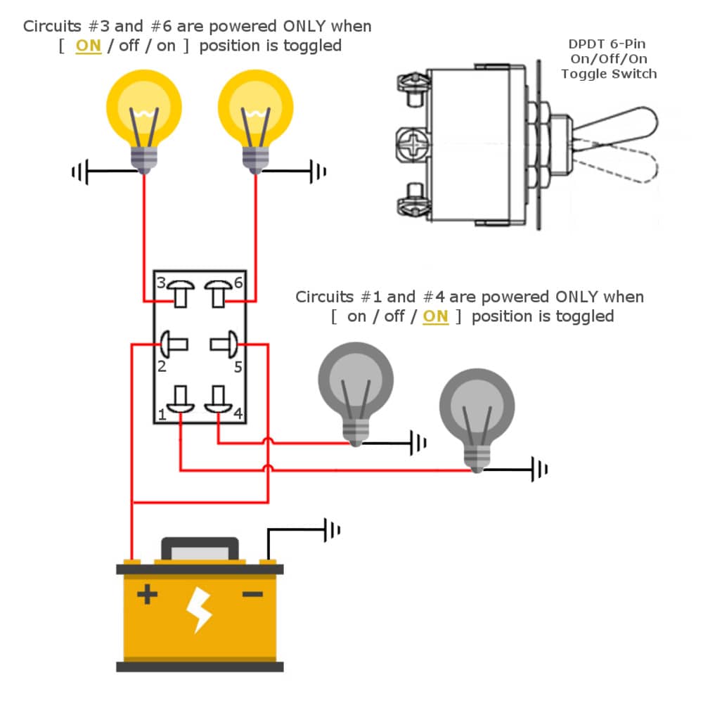
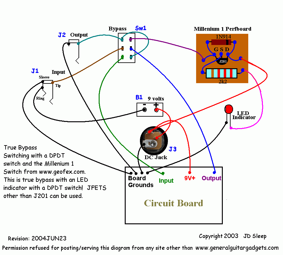
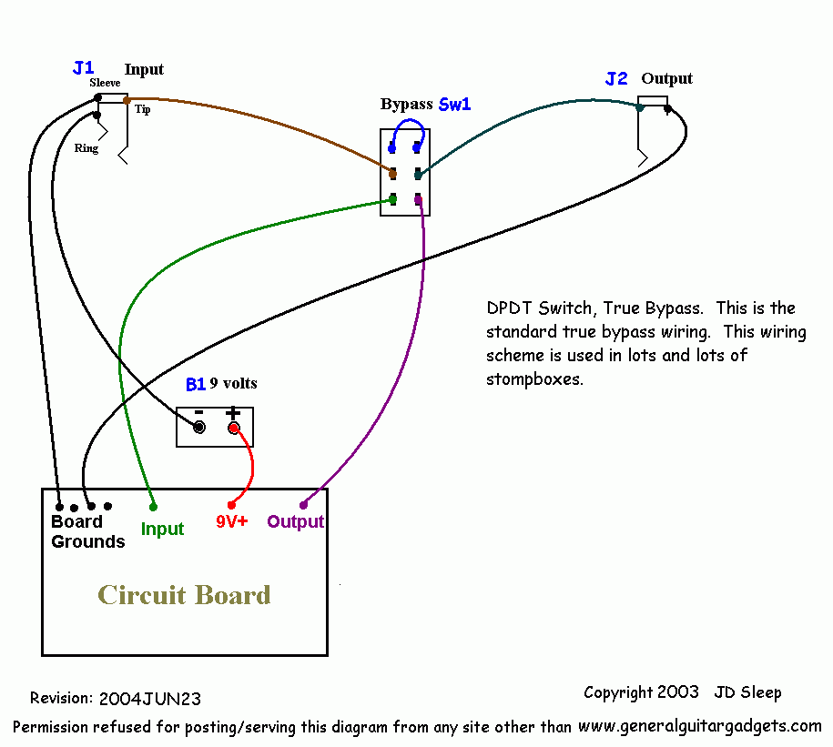
The DPDT switch schematic is essentially a roadmap for electricians and DIY enthusiasts alike. It's a visual representation of how to connect the various wires to the switch terminals to achieve the desired function. Understanding this diagram is crucial for safe and effective implementation of DPDT switches.
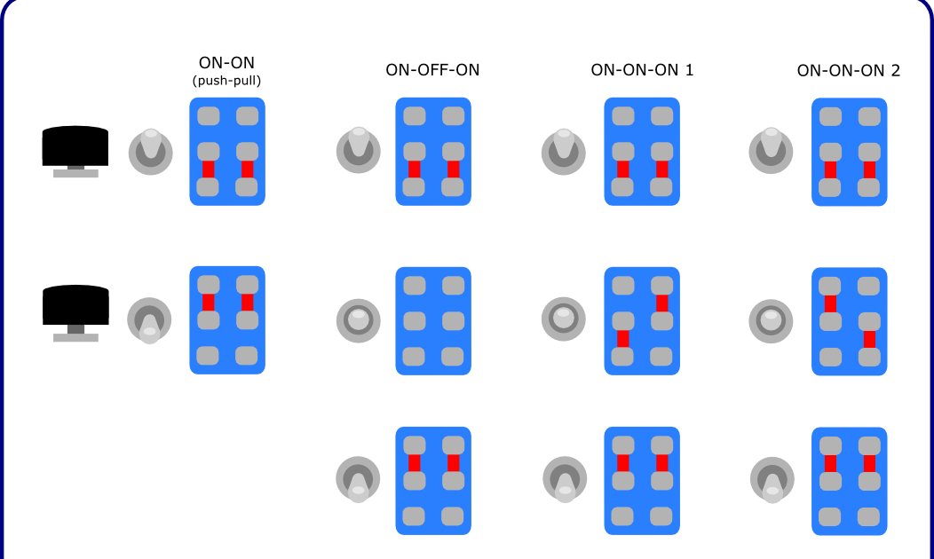
While the inner workings of a DPDT switch might appear daunting, the basic principle is quite simple. The switch has two separate poles (sets of contacts) that can be thrown (connected) to two different throws (output terminals) for each pole. This arrangement allows for the simultaneous control of two separate circuits, a capability that distinguishes it from single-pole switches.
The history of the DPDT switch is intertwined with the development of electrical systems. As electrical devices became more complex, the need for more sophisticated switching mechanisms arose. The DPDT switch emerged as a solution for controlling multiple circuits efficiently, contributing significantly to the evolution of electrical engineering.
DPDT switch wiring diagrams play a critical role in various applications. They are indispensable for electricians, technicians, and even homeowners undertaking electrical projects. Without a proper schematic, the chances of miswiring the switch increase dramatically, potentially leading to malfunctioning devices or even safety hazards.
A DPDT switch connection diagram typically shows the switch with its six terminals clearly labeled. The connections for the input power, the two outputs for each pole, and the common terminals are indicated. This diagram is the key to understanding how the switch functions and how to connect it correctly.
One major issue associated with DPDT switch configurations is incorrect wiring. A misplaced wire can lead to unintended behavior or even short circuits. Therefore, meticulously following the wiring diagram is paramount for proper operation and safety.
Three key benefits of using DPDT switches include versatility, control, and efficiency. Their versatile nature allows them to be used in a variety of applications, from reversing motor direction to switching between different audio sources. The control they offer over multiple circuits simplifies complex switching tasks, and their efficient use of wiring minimizes clutter and simplifies installations.
Before working with a DPDT switch wiring guide, always disconnect the power source to avoid electrical shock. Gather the necessary tools, including wire strippers, screwdrivers, and the switch itself. Follow the specific DPDT switch diagram carefully, ensuring that each wire is connected to the correct terminal.
Advantages and Disadvantages of DPDT Switches
| Advantages | Disadvantages |
|---|---|
| Versatile application | More complex wiring than SPST |
| Controls two circuits simultaneously | Can be more expensive than simpler switches |
| Efficient wiring | Requires careful attention to the wiring diagram |
Best Practices for Implementing DPDT Switch Wiring Diagrams:
1. Always double-check the wiring diagram before connecting any wires.
2. Use appropriate wire gauge for the intended application.
3. Secure all connections tightly to prevent loose wires.
4. Test the circuit thoroughly after installation.
5. Label the wires for future reference and troubleshooting.
Frequently Asked Questions:
1. What does DPDT stand for? - Double-pole, double-throw.
2. How many terminals does a DPDT switch have? - Six.
3. Can a DPDT switch be used to reverse motor direction? - Yes.
4. What is the purpose of a DPDT switch wiring diagram? - To guide correct wiring.
5. What are the common applications of DPDT switches? - Motor control, switching between audio sources, and various other applications.
6. What happens if a DPDT switch is wired incorrectly? - Malfunction or short circuit.
7. How can I troubleshoot a DPDT switch wiring issue? - Check the wiring diagram and ensure all connections are secure.
8. Where can I find DPDT switch wiring diagrams? - Online resources, product manuals, and electrical textbooks.
Tips and Tricks: Use colored wires to easily identify different circuits. Take clear pictures of the wiring before and after installation for future reference.
In conclusion, the DPDT switch wiring diagram is an essential tool for anyone working with electrical circuits. Its understanding unlocks the full potential of this versatile switch, enabling the control of multiple circuits with precision and efficiency. From simple home projects to complex industrial applications, the DPDT switch, guided by its wiring diagram, plays a crucial role in modern electrical systems. Mastering the DPDT switch diagram empowers you to confidently tackle various electrical projects, ensuring safety and functionality. Explore the world of electrical control and discover the endless possibilities that the DPDT switch has to offer. Take the time to understand the diagram, follow best practices, and unlock the power of this versatile component.
Maximize your san diego space with a murphy bed
Maybank car loan repayment methods
Andrew harris tiktok snapchat presence explored


