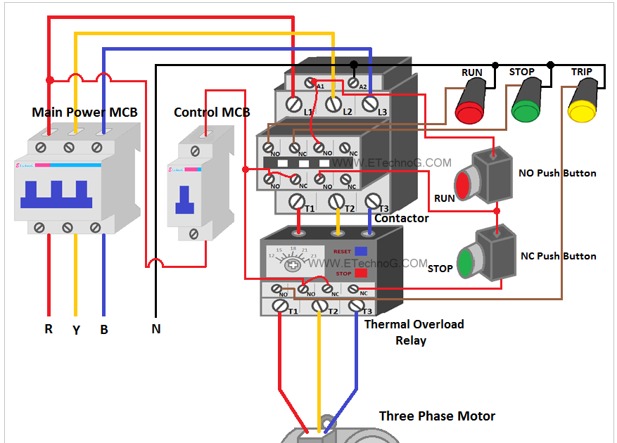
Unlocking Motor Control: Your Wiring Diagram Guide
Ever feel like you're staring at a cryptic puzzle when tackling an electrical project involving a motor? Understanding motor control wiring diagrams is the key to unlocking that puzzle and empowering you to confidently work with electrical systems. Whether you're a DIY enthusiast rewiring a garage workshop or a professional electrician installing complex industrial machinery, a firm grasp of these diagrams is crucial. This guide will take you through the essentials of motor control schematics, from their history and importance to practical tips and troubleshooting.
Motor control wiring diagrams, often available in PDF format, are essentially visual roadmaps of an electrical circuit. They detail how power flows from the source, through various control components like relays and switches, and ultimately to the motor itself. These diagrams use standardized symbols to represent each component, providing a universal language for electricians and technicians worldwide. Without these blueprints, even a seasoned electrician would struggle to understand the complex interplay of components in a motor control circuit. They offer a clear, concise, and organized representation of the system, allowing for efficient troubleshooting, installation, and maintenance.
The history of these diagrams is intertwined with the development of electric motors and control systems themselves. As motors became more sophisticated and integrated into various industrial applications, the need for a standardized way to represent their wiring became paramount. Early diagrams were often hand-drawn and specific to a particular installation, leading to potential confusion and errors. The standardization of symbols and the emergence of the PDF format for easy sharing and printing have revolutionized the field, enabling efficient communication and collaboration among engineers and technicians.
The core purpose of a motor control schematic is to provide a clear and accurate depiction of the electrical connections within a motor control system. They are critical for several reasons. Firstly, they are essential for safe installation. By precisely outlining the connections, they minimize the risk of incorrect wiring, which could lead to short circuits, motor damage, or even personal injury. Secondly, they facilitate troubleshooting. When a motor malfunctions, a wiring diagram helps pinpoint the problem area quickly, saving valuable time and resources.
Furthermore, motor control wiring diagrams play a crucial role in system design and modification. When planning a new motor control system or upgrading an existing one, these diagrams serve as the blueprint for the entire process. They help ensure that all components are correctly sized and interconnected for optimal performance and safety. Understanding these diagrams empowers you to analyze existing systems, identify potential weaknesses, and make informed decisions about improvements or modifications.
Benefits of using motor control wiring diagrams include improved safety, efficient troubleshooting, and streamlined system design. For instance, a clear diagram can prevent accidental short circuits during installation, ensuring the safety of the installer and the equipment. In troubleshooting, a diagram can quickly guide a technician to a faulty relay, avoiding hours of unnecessary checks. Finally, using a standardized diagram during the design phase allows for better communication and collaboration among team members, resulting in a more robust and efficient system.
A typical motor control wiring diagram will show the power source, overload protection devices, control relays, start and stop buttons, the motor itself, and any associated sensors or indicators. Lines connecting these components represent the wiring, with different line types indicating different wire gauges or functions.
Best practices for using motor control diagrams include understanding the symbols, tracing the circuit path, and verifying the diagram against the actual installation. Before working on any motor control system, ensure you have the correct and up-to-date diagram for that specific system. Always double-check your work against the diagram to prevent errors.
Advantages and Disadvantages of Using PDF Diagrams
While PDF diagrams offer many advantages, there are also some drawbacks.
| Advantages | Disadvantages |
|---|---|
| Easy to share and print | Can be difficult to edit or modify |
| Universally compatible | Static format - doesn't allow for interactive simulations |
| Preserves formatting across different devices | Can be large files, especially for complex diagrams |
FAQs:
1. Where can I find motor control wiring diagrams? Manufacturer websites, technical manuals.
2. What are the common symbols used in these diagrams? Standardized symbols represent components like relays, switches, and motors.
3. How do I interpret a complex motor control diagram? Break it down into smaller sections, trace the current path.
4. What software can I use to create my own diagrams? CAD software, specialized electrical design software.
5. Are there different types of motor control diagrams? Yes, ladder diagrams, wiring diagrams, schematic diagrams.
6. What are some common troubleshooting techniques using diagrams? Check for open circuits, faulty components.
7. How important are these diagrams for safety? Critical for preventing miswiring and ensuring safe operation.
8. Can these diagrams be used for both AC and DC motors? Yes, with appropriate modifications and symbols.
In conclusion, mastering motor control wiring diagrams is a fundamental skill for anyone working with electrical systems. These diagrams provide a clear roadmap for understanding, installing, maintaining, and troubleshooting motor control circuits. From enhancing safety to streamlining system design, the benefits of using these diagrams are undeniable. By familiarizing yourself with the symbols, best practices, and resources available, you can empower yourself to tackle any electrical project with confidence. Take the time to understand these visual blueprints, and you’ll be well on your way to becoming a proficient and efficient troubleshooter, installer, and designer of motor control systems.
Spick and span seats the ultimate guide to car upholstery cleaning
De haan 14 day weather forecast your guide to planning
Decoding the gs pay scale steps to a higher salary


