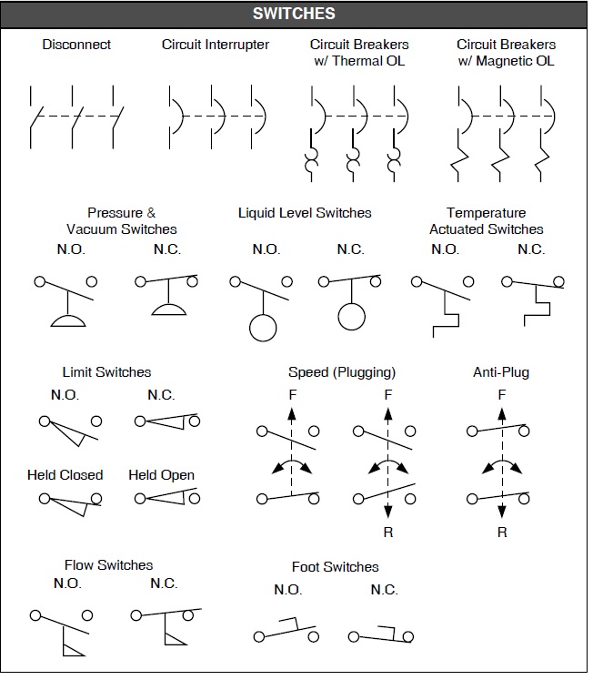
Decoding the Secret Language of Circuitry Switches
Ever peeked at a circuit diagram and felt like you were staring at an alien language? Those cryptic symbols representing switches are more than just squiggles and lines; they're the key to understanding how electricity flows through a circuit. Unlocking the meaning of these switch symbols opens up a whole new world of electronic wizardry, from simple light switches to complex control systems.
Schematic diagrams are the roadmaps of the electronics world, and switch symbols are essential landmarks. They provide a standardized visual language that engineers and hobbyists alike can use to communicate circuit designs effectively. Imagine trying to explain a complex circuit using only words – it would be a nightmare! Switch representations on schematics provide a concise and unambiguous way to represent the function of each switch within a circuit.
The history of these symbols is intertwined with the development of electronics itself. As circuits became more complex, the need for a standardized visual representation became crucial. Early electrical diagrams often used realistic depictions of components, but these proved cumbersome and impractical. The evolution towards simplified, symbolic representations allowed for clearer, more compact diagrams, paving the way for the complex electronic designs we see today.
Understanding switch symbols isn't just for electrical engineers; it's a superpower for anyone interested in tinkering with electronics. Whether you're building a simple circuit or troubleshooting a faulty appliance, knowing what each switch symbol represents is invaluable. It empowers you to interpret diagrams, understand how circuits work, and even design your own electronic creations.
The importance of standardized representations for switches cannot be overstated. It ensures clear communication and avoids misinterpretations that can lead to faulty circuits or even dangerous situations. Imagine the chaos if every engineer used their own unique symbols! Standardized diagrams allow for collaboration, efficient troubleshooting, and the sharing of electronic designs across the globe.
A simple single-pole single-throw (SPST) switch, represented by a line with a break and a small diagonal line, indicates a simple on/off function. A double-pole double-throw (DPDT) switch, on the other hand, is depicted with two sets of connected lines and diagonal lines, allowing for more complex switching configurations.
One benefit of using schematic symbols is clarity. They condense complex information into easily digestible visual cues. For instance, a push-button switch symbol instantly communicates its momentary action compared to a toggle switch, which suggests a maintained state. This visual clarity simplifies troubleshooting and circuit analysis.
Another advantage is universality. These symbols transcend language barriers. An engineer in Japan can understand a schematic drawn by an engineer in Brazil, fostering global collaboration and knowledge sharing. This standardized language allows for the seamless exchange of circuit designs and promotes innovation.
Standardized symbols promote efficiency in design and troubleshooting. By using a common visual language, engineers can quickly grasp the function of each component, reducing the time spent deciphering complex descriptions. This efficiency streamlines the entire design process from initial concept to final product.
Advantages and Disadvantages of Standardized Switch Symbols
| Advantages | Disadvantages |
|---|---|
| Clarity and ease of understanding | Requires learning the symbols initially |
| Universality and cross-cultural communication | Can be overwhelming for complex circuits |
| Efficiency in design and troubleshooting | Subtle variations can sometimes be confusing |
Best practice is to always consult a reliable symbol reference guide. Different standards might have subtle variations, ensuring consistency in your designs.
Frequently Asked Questions:
1. What does SPST stand for? - Single-Pole Single-Throw
2. What is a DPDT switch? - Double-Pole Double-Throw
In conclusion, schematic symbols for switches are the unsung heroes of circuit design. They bridge the gap between abstract electrical concepts and tangible circuit implementations. Mastering these symbols is like learning a new language that unlocks a world of electronic possibilities. By understanding the history, meaning, and practical application of these symbols, you gain the power to analyze, design, and troubleshoot circuits with confidence and precision. So, dive into the fascinating world of schematic diagrams, explore the diverse array of switch representations, and unleash your inner electrical engineer!
Navigating memphis roads your guide to towing services
Understanding the impact of dr chan wing hong
Navigating visa requirements in hua hin and tum


