Decoding Solid State Relay Schematic Symbols
Ever stare at a circuit diagram and feel like you're deciphering hieroglyphics? You're not alone. Electronic schematics can be intimidating, especially when you encounter unfamiliar symbols. One such symbol, crucial for modern electronics, is the solid state relay (SSR) schematic symbol. Understanding this symbol is key to comprehending and designing circuits involving switching high-power loads.
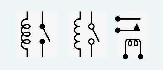
Solid state relays are electronic switches that use semiconductors to control the flow of current. Unlike traditional electromechanical relays, they have no moving parts, making them more reliable and faster. The solid state relay schematic symbol represents this electronic switch in circuit diagrams, providing a visual shorthand for its function. Mastering this symbol allows you to quickly grasp the role of SSRs in a circuit.
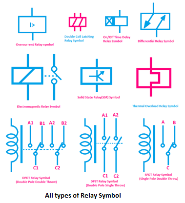
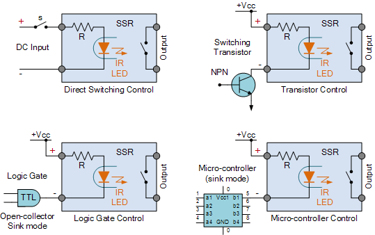
The graphical representation of a solid state relay varies slightly depending on the specific type and manufacturer, but they generally share common elements. These symbols typically depict the input (control) side and the output (load) side, often separated by a gap representing the optical isolation within the SSR. This isolation is a key feature of SSRs, protecting sensitive control circuits from high voltages and currents on the load side.
Imagine needing to control a powerful motor or a high-wattage heater. A traditional relay might struggle with the high currents involved, leading to contact wear and eventual failure. This is where SSRs shine. Their solid-state design allows them to switch these loads quickly and reliably, without the limitations of mechanical contacts. Recognizing the solid state relay schematic symbol in a diagram immediately tells you that such a switching mechanism is in play.
The history of solid state relay schematic symbols is intertwined with the development of semiconductor technology. As transistors and other solid-state devices became more prevalent, the need arose for a standardized way to represent them in circuit diagrams. This led to the evolution of specific symbols for various types of SSRs, reflecting their unique functionalities and internal structures. Understanding this evolution provides valuable context for interpreting these symbols today.
A solid state relay schematic symbol typically includes a triangle representing the input side and two parallel lines representing the output side. Often, there is a circle or other symbol inside to indicate the type of SSR, such as an AC or DC type. The input side is connected to the control circuit, while the output side is connected to the load being controlled.
Benefits of Understanding SSR Schematic Symbols:
1. Circuit Analysis: Quickly identify and understand the role of SSRs in complex circuits.
2. Troubleshooting: Diagnose problems and identify potential faults related to SSRs.
3. Design: Incorporate SSRs effectively into new circuit designs.
Best Practices for Implementing SSRs:
1. Heat sinking: SSRs can generate heat, especially at high currents. Ensure adequate heat sinking to prevent overheating.
2. Input voltage: Use the correct input voltage to control the SSR.
3. Load current: Choose an SSR with a current rating appropriate for the load.
4. Isolation: Ensure sufficient isolation between the input and output circuits.
5. Zero-crossing switching: Consider using zero-crossing SSRs for AC loads to minimize electrical noise.
Advantages and Disadvantages of Solid State Relays
| Advantages | Disadvantages |
|---|---|
| Faster switching speeds | Higher cost compared to mechanical relays |
| Longer lifespan | Voltage drop across the output |
| No moving parts, increased reliability | Sensitivity to transient voltages |
Frequently Asked Questions:
1. What is an SSR? - A solid-state relay is an electronic switch.
2. What are the benefits of using SSRs? - Faster switching, longer lifespan, no moving parts.
3. How do I choose the right SSR? - Consider load current, input voltage, and isolation requirements.
4. What is zero-crossing switching? - Switching at the zero voltage point of the AC cycle.
5. How do I identify an SSR in a schematic? - Look for the characteristic triangle and parallel lines symbol.
6. What are the common issues with SSRs? - Overheating, incorrect input voltage, exceeding current rating.
7. How do I troubleshoot SSR problems? - Check for proper heat sinking, correct input voltage, and load current within limits.
8. Where can I learn more about SSRs? - Manufacturer datasheets, online tutorials, and electronics textbooks.
In conclusion, the solid state relay schematic symbol is a fundamental element in modern circuit design. Understanding its nuances allows you to effectively utilize SSRs in your projects, leveraging their speed, reliability, and isolation capabilities. From controlling high-power industrial equipment to managing sensitive electronic devices, SSRs play a vital role. By familiarizing yourself with the symbol, best practices, and troubleshooting techniques, you can unlock the full potential of these versatile electronic switches and confidently navigate the world of circuit diagrams. Learning to interpret these symbols is not just about reading diagrams; it's about understanding the underlying technology and its applications, empowering you to design and troubleshoot more effectively. So, dive in, explore, and master the language of electronics, one symbol at a time. This knowledge will be invaluable as you continue your journey in the fascinating realm of electronics.
Maximize your malibu boats performance the ultimate guide to parts and service
Behr deckover vs paint for terracotta surfaces the ultimate guide
Fifa 23 the final whistle and a new era of football gaming


