Decoding Circuit Secrets Understanding Electrical Component Symbols and Their Roles
Ever wondered how those squiggly lines and shapes on a circuit diagram translate into a functioning electronic device? They're not just random doodles; they're a universal language that unlocks the secrets of electronics. These symbols represent electrical components, each with a specific role to play in the flow of electricity. Understanding these symbols and their corresponding functions is like learning the alphabet of circuits, opening up a world of possibilities in electronics, from simple circuits to complex systems.
Imagine trying to bake a cake without knowing what the ingredients are or what they do. Similarly, designing or understanding an electrical circuit is impossible without knowing the function of each component. These functions, visualized through standardized symbols, allow engineers and hobbyists alike to communicate effectively and build functional circuits. This graphical representation simplifies complex designs, making them easier to analyze, troubleshoot, and share.
The history of electrical component symbols is intertwined with the development of electrical engineering itself. As the field progressed, the need for a standardized way to represent components became crucial. Early symbols often resembled the physical components they represented, but over time, they evolved into more abstract forms for simplicity and standardization. Organizations like the IEEE (Institute of Electrical and Electronics Engineers) and IEC (International Electrotechnical Commission) have played a significant role in establishing these standards, ensuring consistency across the globe.
These symbols aren't just for professionals; they are essential for anyone interested in electronics. Whether you're a student learning about circuits, a hobbyist building a project, or a professional engineer designing complex systems, knowing these symbols is fundamental. They provide a concise and unambiguous way to represent the function of each component in a circuit, facilitating clear communication and understanding.
Misinterpreting or overlooking a single symbol on a circuit diagram can have significant consequences, leading to malfunctions or even damage. This underscores the importance of accurately understanding electrical component symbols and their associated functions. Precise interpretation is crucial for ensuring that circuits perform as intended and avoids potential hazards.
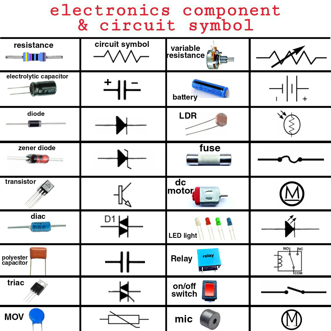
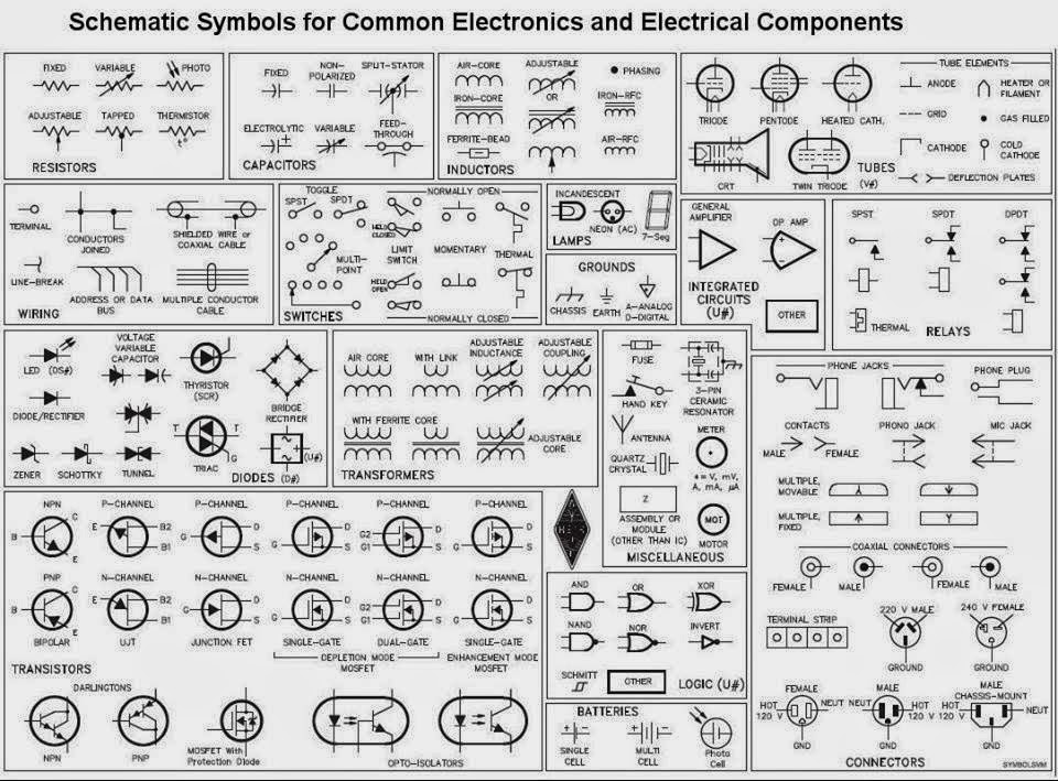
For instance, a resistor, represented by a zigzag line, controls the flow of current. A capacitor, symbolized by two parallel lines, stores electrical energy. And a diode, depicted as an arrow pointing at a line, allows current to flow in only one direction. These are just a few examples of the many components that make up electrical circuits, each with its unique symbol and function.
One key benefit of standardized symbols is their universal recognition. This allows engineers and technicians worldwide to understand and collaborate on circuit designs regardless of language barriers.
Another benefit is the clarity they provide in complex circuits. Imagine trying to decipher a circuit with hundreds of components drawn realistically! Symbols streamline the representation, making it much easier to trace connections and understand the overall circuit function.
Finally, standardized symbols enable efficient troubleshooting. When a circuit malfunctions, these symbols allow technicians to quickly identify the faulty component, saving valuable time and effort.
A simple example is a basic LED circuit. You would need a battery (symbolized by long and short parallel lines), a resistor (zigzag line), and an LED (arrow with two small lines emanating from its base). Connecting these components according to their symbols in a circuit diagram will light up the LED.
Advantages and Disadvantages of Standardized Electrical Component Symbols
While the benefits are numerous, it is important to acknowledge some challenges:
| Advantages | Disadvantages |
|---|---|
| Universal understanding | Initial learning curve |
| Simplified representation of complex circuits | Potential for misinterpretation if not learned thoroughly |
| Efficient troubleshooting | Constant updates and additions to standards require ongoing learning |
Best Practice: Always double-check the symbol's meaning in a reliable reference before implementing it in your design.
Real-world Example: In a smartphone, numerous tiny components, each with its specific symbol and function, work together seamlessly to provide various functionalities, from processing data to transmitting signals.
Challenge: Keeping up with the constantly evolving symbols and standards. Solution: Regularly consult updated resources and industry publications.
FAQ: What is the symbol for a transistor? Answer: A transistor has different symbols depending on its type (NPN or PNP), but they generally include three terminals and an arrow indicating the direction of current flow.
Tip: Use online circuit simulators to visualize how different components and their symbols work in a circuit.
In conclusion, the world of electronics relies heavily on the precise language of electrical component symbols and functions. From the simplest resistor to the most complex integrated circuit, each component plays a crucial role in the operation of electronic devices. Understanding these symbols is essential for anyone involved in designing, building, or troubleshooting circuits. The benefits of standardized symbols, such as universal comprehension and simplified circuit representation, are invaluable. As technology advances, so too will the complexity of electrical components and their associated symbols. Continuous learning and adherence to best practices are crucial for keeping pace with these advancements and ensuring accurate and efficient circuit design. By mastering the language of electrical symbols, you unlock the ability to design, understand, and troubleshoot the electronic devices that shape our modern world. So, embark on this journey of discovery, explore the fascinating world of electrical components, and empower yourself with the knowledge to bring your electronic creations to life.
Behr exterior red paint transforming your homes curb appeal
Mastering your boats electrical system with waterproof rocker switch panels
Josh hutchersons career highlights and impact


.jpg)


